Evil test vectors
Sometimes the best test vectors are the ones that make you question what they are testing and why you're failing.
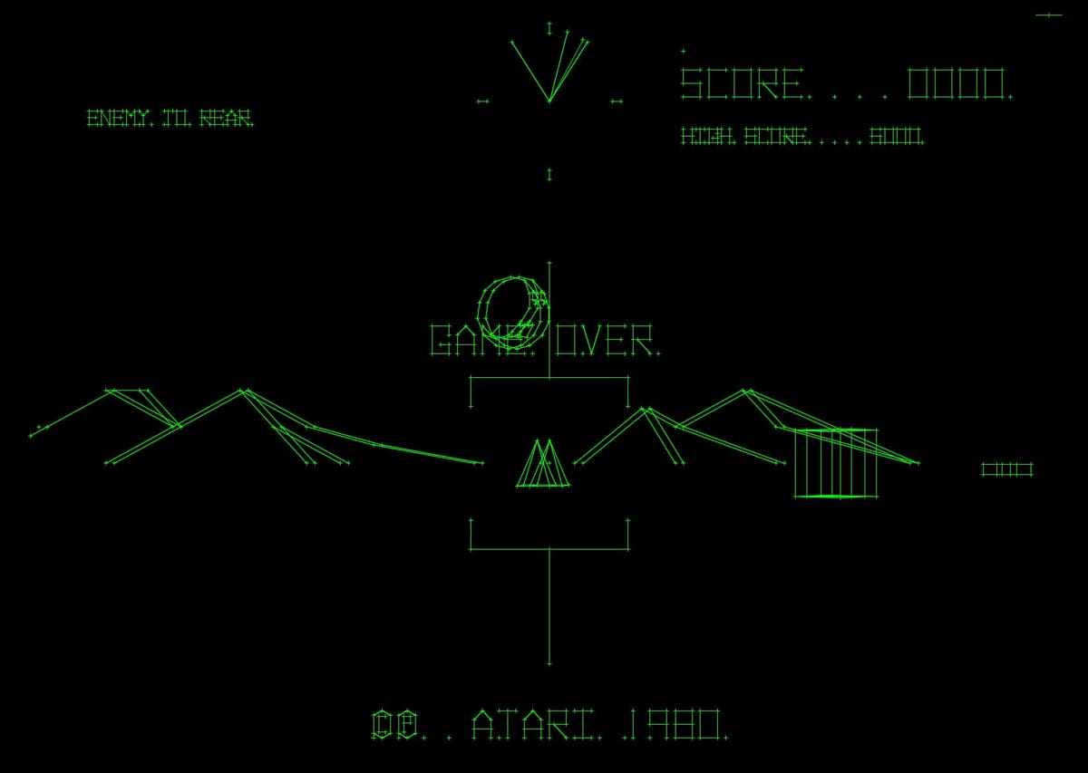
Vector games are one of my hobbies and I've been working on emulating them in various ways such as using MAME to drive a Vectrex or Tektronix vectorscope. But this always involves software, sometimes massive amounts of software, to run the game. I had the idea of instead writing a Verilog 6502 that could run the original game ROMs and it mostly works! Good enough to run BattleZone on the FPGA or very slowly in the iverilog simulator.
Then I found a collection of millions of test vectors for the 65x02 by Tom Harte, which has thousands of tests for each instruction, along with the bus cycles that occur when the CPU executes those instructions.
I built a iverilog test harness that could run the instruction streams and validate the results, and as expected, my 6502 failed many many of them. So I hacked away until all* of the instructions passed including the hard ones that involve wrapping around the zero-page on certain addressing modes, but there was only one JSR instruction test that failed.
The CPU state for the test is:
PC = 0x017B
S = 0x7D
RAM[0x017B] = 0x20 // JSR
RAM[0x017C] = 0x55
RAM[0x017D] = 0x13
RAM[0x0155] = 0xAD
When this executes it looks like it should be a JSR (0x1355) but the test vector says the destination should be 0x0155 instead.
Turns out, I wasn't the only person to run into this problem and it is an evil (but accurate!) test vector. First thing to note is that the stack is located from 0x100 to 0x1FF, so even though it is one byte it is referencing the higher address. This means that it is pointing to the second byte of the JSR instruction at 0x17D!
The second thing to note is that the 6502 doesn't read the entire three byte instruction at once. The bus is 8-bits wide, so the cycles are:
- Read the first byte
0x20and decode it as aJSR. - Read the next byte
0x55as the low-bits of the destination address. - Pushes the high byte of the PC
0x01, writing it to0x017Din memory and decrementingS. - Push the low byte of the return address minus one
0x7D, writing it to0x017Cand decrementingSagain. - Then fetch the third byte of the instruction, the high byte of the destination address, from
0x017D, which was overwritten in cycle 3, so it reads back0x01 - Set the PC to
0x0155
This self modifying code doesn't happen in practice in the arcade games that I'm emulating (since they store their code in ROM and don't execute from the stack region), so I'm not going to fix it in my hardware right now. It's not really evil, it's more subtle and the sort of test vector that really makes you think about the underlying system that is being tested.
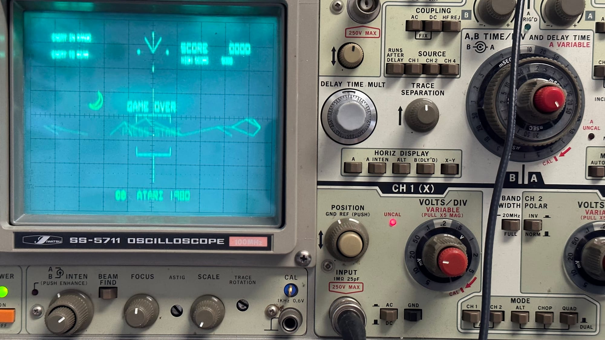
And now the 6502 softcore plus Verilog versions of the "MathBox" and "Digital Vector Generator (VecGen)" hardware is good enough to run the original, unmodified BattleZone ROM. I'm working on a better PCB design for the DAC's since the current breadbard version is very noisy and doesn't result in
*: I don't have correct semantics for the BCD instructions. Some documents claim that the N and V flags are undefined on the 6502 so my tests mask them out on those vectors. And the BattleZone code does not use the flags when it enables decimal mode with SED, and it switches back to non-decimal mode with CLD before performing any SBC subtractions, so I think they didn't want to depend on it either.